
Aim:
(i) To standardize the Orifice meter device (by assessing the constants K and n, presumptuous the real discharge Qa = K*Hhgn).
(ii) To compute the coefficient of discharge (Cd) of the specified orifice meter for diverse rates of flow.
(iii) To revise the deviations of Cd and release with regards to the head by maneuverings the subsequent graphs.
Cd Vs HHg
Qa Vs Log HHg (to find K and n )
Qa Vs HHg (using K and n values)
Apparatus:
- Measuring tank of size 0.6 * 0.6 * 0.8 with drain valve, scale arrangement.
- Stop Watch
- Orifice meters
- Differential mercury manometer
| S.No: | Pipe Diameter, mm | Orifice Diameter, mm | |
|
1.
2.
3. |
20
25
40 |
13.41
16.77
26.83
|
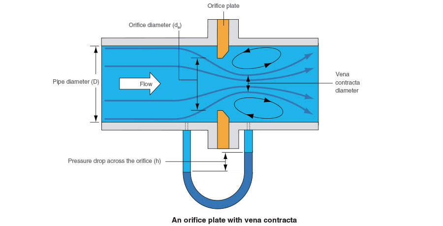
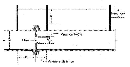
Theory:
Orifice meter or orifice plate refers to the tool utilized for assessing the rate of flow of a fluid via a pipe. It operates on the similar principle as a venturimeter. It incorporates a flat circular plate which consists a circular sharp edged hole known as orifice, which is concentric with pipe. The orifice diameter is approximately 0.5 times the diameter of the pipe. A differential manometer is joined at section 1 which is at a approximate space of about 1.5 to 2 times the pipe diameter upstream from the orifice plate, and at section 2, which is at a space of about half the diameter of the orifice on the downstream side from the orifice plate.
The net discharge
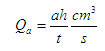
a – Area of measuring tank in cm2
h – Height differences in piezo meter in cm.
t – Time period to accumulate water for a height difference of h cm, measured in seconds.
Theoretical discharge,
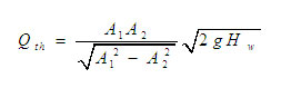
Where
A1 – The area at inlet side in cm2
A2 – The area at throat in cm2
Hw – Head difference in the manometer, converted to cm of water.
g – Acceleration due to gravity (9.81).
Coefficient of discharge,

Calibration of Venturi meter
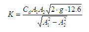
The equation
Qa = Cd x Qt can be written as
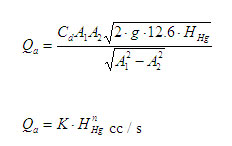
Where,
Observations:
| Sl No | Differential head in cm. of mercury
HHg |
Head difference
Hw, in cms of water |
Actual Discharge,
Qa, cm3 / s |
Log Qa | Log HHg | Qa = K HHg n
cm/sec |
|
1
2
3
4
5
|
Calibration Table
| Sl No | Differential head in cm. of mercury
HHg |
Head differenceHw,in cms of water | Actual Discharge,Qa,
cm3 / s |
Log Qa | Log HHg | Qa = K HHg n
cm/sec |
| 1
2 3 4 5 |
Procedure:
(i) Shut the valves of inlet pipe, Orifice meter pipe line and manometer.
(ii) The gate valve of the pipeline chosen for the experimentation is unlocked.
(iii) Needle valves of the equivalent manometer & Orifice meter are also opened
(iv) Regulate the control valve put at the exit side of the Orifice to a necessary flow rate and preserve the flow.
(v) Mark down the readings of manometer & time for 10cm rise in measuring tank.
(vi) Regulate the gate valve and repeat the experiment.
Maintenance
- After the completion of experiment close the inlet valve and open all the gate valves & needle valves then close them.
- Deplete the water from measuring tank after the completion of the experiment.
Calibration
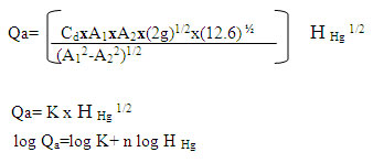
Plot the given graph log Qa Vs log H Hg ,Y intercept symbolizinglog K and slope symbolizes n
The calibration graph Qa Vs H Hg can be illustrated
H Hg =(H1-H2) in Hg manometer.
Find Qa values corresponding to manometer readings
Result:
The coefficient of discharge Cd=
Find the value of K and n from graph