
There are various properties of a beam that an Engineer ought to know about as they direct beam conduct when exposed to the load and finally represent probable regions, methodologies, and components for failures and breakdowns. The principle ones being:
Second moment of the territory (additionally indicated to as the second moment of inactivity): this relies on upon the cross section profile of the beam and is a appraise of the resistance of the state of the beam to bowing and bending
Bending moment: normally outlined on a bending moment chart, and frequently related the diversion of the beam, can be utilized to ascertain areas subject to greatest bending forces and strengths and subsequently destined to yield. It additionally represents which segments of the beam are in compaction or strain.
Beam deflection: beam deflection has a tendency to be undesirable and associates to the bending moment
Shear graphs: these are utilized to outline stretch concentration along the beam and give a way to recognize zones of most extreme shear forces where the beam will probably have breakdown by shear.
Second moment of area
The second moment of area (I) is a characteristic of the shape utilized to forecast the resistance of the beam to deflection and bending. It is assessed from the objective cross sectional region of the beam and recounts the profile weight to the impartial axis (this being a segment where the beam is exposed to neither tension nor compaction, as shown in the diagram below. It is based on the course of loading; for majority of beams except both void and concrete box and circular regions, the second moment of area will be diverse when loaded from a level or perpendicular direction.
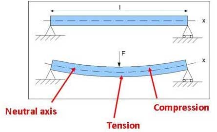
Figure: 1. Minimally upheld beam of length l with no force 2. Simply supported beam exposed to point load (force) F at centre creating bending.
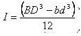
The second moment of area can be assessed from first principles for any cross section profile using the following equation:
On the other hand, for common beam profiles standard formula are used:
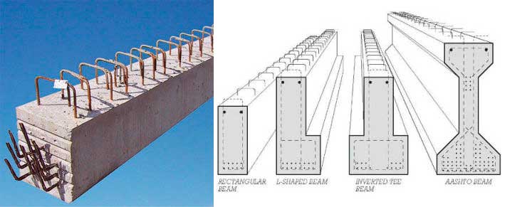
I – Beam/ Universal beam

Figure- I beam cross section profile while loading parallel to the web
The I – beam also known as the Universal beam has the most effective cross sectional profile as chiefly majority of its material is situated away from the impartial axis giving a high second moment of area, which in turn amplifies the stiffness, thus, resistance to bending and deflection. It can be assessed using the formula:
As shown in figure above this is only suitable for loading parallel to the web, as loading perpendicular to the web would be less efficient.
Box section
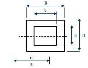
Figure: Box section cross-section profile
The box section has the best competent profile in loading both horizontally and perpendicularly. It has a lower value for second moment of area so is less rigid. It can be assessed by using the formula:
Bending moment and shear diagrams
Bending moment and shear diagrams are usual drawn next to a illustration of the beam profile as illustrated in the figure below, this allows a precise demonstration of the beams properties.
a) Symbolizes a beam exposed to a consistently allocated load (udl) of magnitude w, across the length, l. The Total force on beam being wl.
The beam is basically uphold with reaction forces R.
Distance x represents any point along the beam.
b) Shear force illustration demonstrates the areas of maximum shear, for this beam these associate to the reaction forces.
The slope of the shear force figure is equivalent to the degree of the allocated load.
A positive shear force will lead the beam to turn around clockwise and a negative shear force will manipulate the beam to make movements in an anticlockwise direction.
c) Maximum bending moment happens when no shear forces subsists on the beam.
As the beam is neatly held up, that is only exposed to perpendicular reaction forces; no bending moment is practiced at these points. If the beam were constrained as in a cantilever position then bending moments would be subjected at either of the ends Correlating to the illustration of beam loading, shear force and bending moments highest and values at distance x alongside the beam can be measured with the following formula:
Reaction force and maximum shear force and Shear force at distance x
![]()
Maximum bending moment and Bending moment at distance x
![]()
Maximum deflection and Deflection at distance x
![]()
These recipes are particular to this beam circumstance that is a consistently circulated weight with straightforward backings as appeared. For a cantilever beam, or one with changing degrees of flexibility at the backings (this indicates to the restraints in the flat direction exposing the beam to a turning moment at this segment) then unique equation will be required. All equation can be figured from first standards yet for simplicity into tables, for example, those contained in “Roark’s formulas for strain and stressed” can be used.
The formulas for greatest beam deflection, ?MAX and deflection at the distance x, ?x are appeared to be dependant on the Young’s modulus, E and second moment of the area, I, where as shear force and twisting moment are autonomous of these beam qualities.