
Objective: For assessment of shear modulus of material of specified wire
Tool and equipment
1. Torsion Pendulum.
2. Cylindrical wire.
3. Stop watch.
4. Venire Calipers.
5. Screw gauge.
6. Meter scale.
Sample
- Brass wire
- Steel Wire
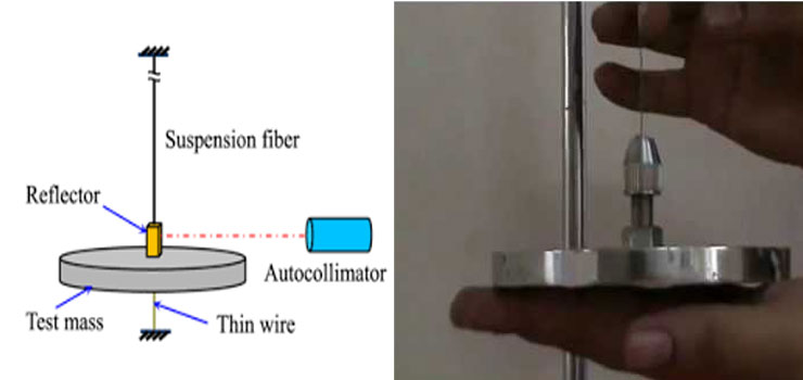
Torsion Pendulum Apparatus
The torsion pendulum apparatus basically comprises of a Torsion pendulum laden in the foam of disc and a thin wire and secondly a bracket for hanging the Pendulum. In this process, we need two matching cylindrical weights which we can mount on the disc; which helps in shifting the moment of inertia of the pendulum.
Principle of Test
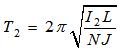
In case of small oscillations of the disc, it is in simple harmonic motion and the formula for simple pendulum holds good.
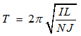
Where T= period of oscillation in sec
I = Mass moment of inertia of the rotating system about the longitudinal axis of wire.
L= Length of the wire between its grips.
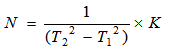
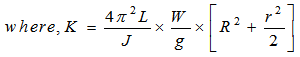
N = Modulus of rigidity (Shear modulus).
d= diameter of the given wire in the test, N is found out as given below if other quantities are known.
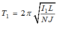
Suffices 1 and 2 refer to those situations when no cylindrical weight is augmented on to the disc and when anticipated cylindrical weights are augmented.
We have,
From which it ascertains:
![]()
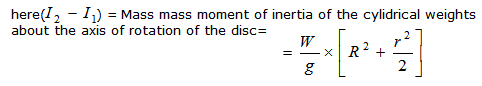
Where W = Total weight of cylinders added to the disc.
g= Acceleration due to gravity.
r= Radius of cylindrical weights.
R = distance from centre of cylinder of the cylindrical weight to centre of wire
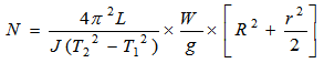
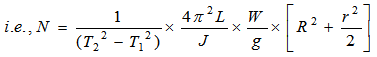
Thus from equations (4) and (5)
Process
The wire for the experimentation is fastened at its foundation to the disc and its apex to the bracket. After that, the disc is turned, trough a small a le and discharged reclusive of the cylindrical weights on it. Time for a number oscillation (Say20) is calculated with the help of the stopwatch. Now, the cylindrical weights are latched on the disc and the new time for the similar quantity of oscillations of the disc is calculated. The experimentation is undertaken for wide assortment of wires with varying lengths.
Observation
The observation is tabularized.
Calculations

Result
Modulus of rigidity (N) of the material of the specified wire (steel)=_________ N/mm2
Modulus of rigidity (N) of the material of the specified wire (steep=-_________N/mm2
Questions
1. What are the tests that can be used for finding modulus rigidity of materials?
2. The period of oscillation increases as the length of pendulum. Is this statement correct or not?
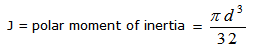
3. What is the different between plane moment of Inertia and polar moment of inertia?
4. What is the use of cylindrical weights in Torsion Pendulum?
5. Define mass moment of Inertia?
6. What is the type of stress developed in the specimen subjected to torsion?
1. Name the tests which can be utilized for finding modulus rigidity of materials.
2. The period of oscillation increases as the length of pendulum. True or False?
3. State the differences between plane moment of Inertia and polar moment of inertia.
4. Explain the utilization of cylindrical weights in Torsion Pendulum?
5. Give definition of mass moment of Inertia.
6. State the type of stress developed in the sample exposed to torsion?