
Mississippi State Highway Department planned this test and is material to hot blend outline of bitumen and totals of most extreme size 2.5 cm. In India, bituminous solid blend is normally planned by Marshall Method. This test is widely utilized as a part of routine test programs for the clearing occupations. The steadiness of the blend is characterized as a most extreme load conveyed by a compacted example at a standard test temperature of 600C. The stream is measured as the deformation in units of 0.25 mm between no heap and greatest load conveyed by the example amid stability test (stream esteem may likewise be measured by distortion units of 0.1 mm). This test endeavors to get the ideal fastener content for the total blend sort and additionally traffic intensity. This is the test which contributes us to draw Marshall Stability versus % bitumen.
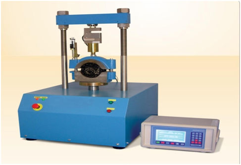
Test Apparatus
The apparatus for the Marshall Stability test comprises of the following procedures:
1. Sample mould assembly consisting mould cylinders 10.16cm width by 6.35cm stature, foundation plate and extension collars.
2. Sample extractor for extracting the compressed sample from the mould. A suitable bar is necessary to allocate load from the extension collar to the upper proving ring connection while removing the sample.
3. Compaction hammer which has a flat spherical tamping face 4.5kg sliding weight manufactured to deliver a discharge of 45 cm.
4. Compaction pedestal comprising of a dimensions 20×20×45 cm wooden block capped with 30×30×2.5 cm MS plate to support the mould assembly in point during compression. Mould holder is given comprising of spring tension device premeditated to hold compression mould in place on the compaction pedestal.
5. Breaking head: this comprises of upper and lower cylindrical segments or test heads consisting an internal radius curvature of 5 cm. the longer segment is connected on a base consisting two vertical guide rods which ease addition in the holes of upper test portion.
6. Loading Machine
7. Stacking Machine: It is furnished with a rigging framework to lift the upward bearing. Pre-aligned proving ring of 5 tons limit is settled on the upper end of the device, example confined in the test head is set in the middle of the base and the demonstrating ring. The heap jack creates a uniform vertical snapshot of 5 cm for each moment. Machine is fit for turning around its minute descending moreover. This encourages satisfactory space for putting test head framework after one example has been tried.
8. Flow meter comprises of guide, sieve and gauge. The activating pin of the gauge glides esoteric the guide sleeve with an insignificant amount of frictional opposition. Minimum count of 0.025 mm is acceptable. The flow value refers to the aggregate perpendicular upward movement from the original position at nil load to value at greatest load. The dial gauge of the flow meter has to be capable to compute precisely the total perpendicular moment upward.
In toting to above the following general tools are also necessary:
- Oven or hot plate
- Water bath
- Thermometers of range up to 200oC with sensitivity of 2.5oC
- Different other equipment like containers, mixing and handling tools etc.
Preparation of Test Sample
1. 1200 grams of totals blended in the sought extents is measured and warmed in the broiler to the blending temperature.
2. Bitumen is augmented at the blending temperature to deliver consistency of 170 ± centi-stirs at different rates.
3. The materials are blended in a warmed skillet with warmed blending devices.
4. The blend is taken back to the broiler and warmed to the compacting temperature (to deliver consistency of 280±30 centi-stirs).
5. The blend is then set in a warmed Marshall shape with a neckline and base and the blend is spaded around the sides of the form. A channel paper is set under the specimen and on top of the example.
6. The mould is put in the Marshall compaction platform
7. The material is compacted with 50 blows of the mallet (or as determined), and the specimen is modified and compacted in the other face with same number of blows.
8. After compaction, the mould shall be inverted. With neckline on the base, the base is expelled and the example is separated by pushing it out the extractor.
9. The specimen is permitted to remain for the couple of hours to cool.
10. The mass of the example in air and when submerged is utilized to quantify the thickness of example, in order to permit, estimation of the void properties.
| Sample no | Weight in air(g) | Weight in water(g) | Specific gravity
|
| 1 | |||
| 2 | |||
| 3 |
| Sample | Softening point(0C)
|
| 1 | |
| 2 |
Test Procedure
1. The samples are heated to 60 ±1oC r in a water bath for approximately30-40 minutes or in an oven for at least 2 hours.
2. The samples are detached from the water bath or oven and positioned in the lower portion of the breaking head. The upper portion of the breaking head of the sample in placed and the total assembly is kept in position on the testing machine.
3. The flow meter is positioned over one of the post and is regulated to read nil.
4. Load is exerted at a rate of 50 mm per minute until the greatest load reading is achieved.
5. The maximum load reading in Newton is read. At the same instant the flow as marked on the flow meter in units of mm was also recorded.