
Francis Turbine refers to an Inward Flow Reaction Turbine consisting Radial Discharge at Outlet that is 0. Modern Francis Turbine is a blended flow type turbine that is Water sips through the runner of the turbine in the radial course and leaves the runner in the axial direction).
Radial Flow Turbines refers to those type of turbines in which the water flows through in the Radial Direction. In Francis Turbine the water flows from outward direction to inward direction from the runner (Inward Flow Radial Turbine). Reaction Turbine refers to that the water at the inlet of the Turbine retains some extent of Kinetic Energy as well as Pressure Energy.
Construction
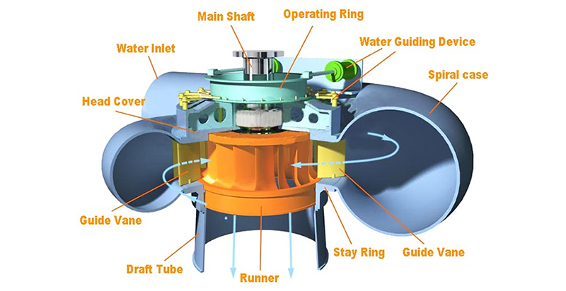
The chief parts of the Francis Turbine are:
Casing
The runner is totally shut in an air-tight spiral casing. The casing and runner are every time completely filled up with water.
Guide Mechanism
It basically comprises of a spherical wheel all-round the runner of the turbine. The stationary guide vanes are permanently fixed on the guide wheel. The guide vanes permit the water to strike the vanes connected on the runner exclusive of the shock at inlet. Additionally, the breadth amongst the two neighboring vanes could be changed so that volume of water striking the runner could be varied.
Runner
By runner, we mean a circular wheel on which a sequence of Radial Curved Vanes is connected. The vanes are shaped in such a way that the water sips and leaves the runner exclusive of shock.
Draft Tube
The pressure at the end of the runner of Reaction Turbine is normally fewer than atmospheric pressure. The water at the end couldn’t be unswervingly discharged to the tail race. A tube or pipe of regularly augmenting area is utilized for liquidating water from the end of turbine up to the tail race. This tube of augmenting area is known as Draft Tube. One end of the tube is joined to the outlet of runner whereas the other end is partially immersed beneath the level of water in the tail-race.
Significant relations for Francis Turbines
1. The ratio of the wheel of to its diameter is given as ![]() . The value of n varies from 0.10 to 0.40.
. The value of n varies from 0.10 to 0.40.
2. The flow ratio is given as  and varies from 0.15 to 0.30.
3. The speed ratio ![]() varies from 0.60 to 0.90.
varies from 0.60 to 0.90.