A box girder (also known as tubular girder) is a girder that forms an enclosed tube or hollow box like structure with multiple walls. The proceeding with development of roadway system all through the world is generally the consequence of awesome increment in movement, populace and broad development of metropolitan urban territories. This extension has prompt to many changes in the utilization and improvement of different sorts of scaffolds and bridges. The bridges sort is identified with giving most extreme proficiency of utilization of material and development method, for specific traverse, and applications. As Span builds, dead load is an essential expanding element. To decrease the dead load, pointless material, which is not used to its full limit, is evacuated out of segment, this outcomes in the state of box girder or cell structures, contingent on whether the shear disfigurements can be disregarded or not. Traverse range is more for box connect girder as contrast with T-bar Girder Bridge bringing about similarly lesser number of wharfs for a similar valley width and consequently brings about economy.
A box girder is framed when two web plates are connected by a typical spine at both the top and the base. The shut cell which is framed has a much more noteworthy torsional solidness and quality than an open area and it is this component which is the standard purpose behind picking a case girder arrangement.
Enclose girders are seldom utilized structures (box sections are some of the time utilized yet these are pivotally stacked as opposed to in stacked in twisting). They might be utilized as a part of exceptional conditions, for example, when burdens are conveyed whimsically to the bar pivot
Box girders can be all around connected from the perspective of load conveying, to their aloofness in the matter of whether the twisting minutes are certain or negative and to their torsional firmness; from the perspective of economy.
Historical development of box girder
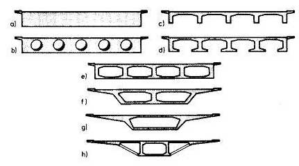
The main box girder cross segment had deck sections that cantilevered out just somewhat from the crate partition appeared in figs a to e. With the pre-stressed concrete the length of cantilever could be expanded. The high shape work costs brought about a lessening in the quantity of cells fig (f, g, h). Keeping in mind the end goal to lessen the construction loads to least conceivable degree or to require just a single longitudinal girder in working states even with different traffic paths
It was just with the improvement of high quality pre-stressing steel that it got to be distinctly conceivable to traverse longer separations. The initially pre-stressed solid extensions, a large portion of I-cross areas were constructed towards the finish of the 1920’s.The extraordinary leap forward was accomplished simply after 1945. “THE SCLAYN” connect over the waterway Maas, which was worked by Magnel in 1948, was the principal ceaseless pre-stressed solid box-girder connect with 2 ranges of 62.70m. In taking after years the proportion of wages to material expenses climbed forcefully. This subsequently moved the accentuation of improvement of development technique. The container girder cross-segment developed basically from the empty cell-deck scaffold or T-bar Bridge. The augmenting of the pressure zone that started as an auxiliary prerequisite at the focal docks was in the stretched out all through the whole length of scaffold due to points of interest transverse load-conveying attributes.

Image: Evolution of Box Girder
The traversing of extensions and bridges began with straightforward sections. As the traverses expanded, the plan profundity of chunk is likewise expanded. It is realized that material close focus of gravity contributes next to no for flexure and consequently can be expelled. This prompts to bar and chunk frameworks. The support in base globule of pillar gave ability to malleable powers and top section concrete, the ability to oppose the pressure. They framed a couple to oppose flexure.
As the width of slab is expanded more number of longitudinal girders are required bringing about lessening of firmness of bars in transverse bearing and moderately high transverse shape. The networks of pillars get opened out spreading rapudly from top slab. Under high transverse twisting these will never again be in their unique position. To keep it in their unique position the globules at base ought to be entwined which thus prompts to advancement of box girder. Long traverses with more extensive decks and flighty stacking on cross-area will endure in ebb and flow in longitudinal and transverse bearing creating substantial twisting of cross-segment. Henceforth the scaffolds ought to have high torsional unbending nature keeping in mind the end goal to oppose the bending of cross-segment deck to a base.
Likewise box girders are more reasonable for bigger ranges and more extensive decks, box girders are to be appropriate cross-area. They are rich and thin. Economy and the aesthetics additionally prompt to advancement of cantilevers in top spines and slanted networks in outside cells of box girder. The measurement of cell could be controlled by pre-stressing.
As the traverse and width builds the shafts and base sections are to be attached to keep the geometry which thus prompts to advancement box girder.
Any unusual load will bring about high torsional stresses which will be balanced by the crate area. The investigation of such segments are more muddled due blend of flexure, shear, torsion, contortion. However, it is more productive cross-segment. It is utilized for bigger ranges with wide cross-area. It can be utilized for ranges up to 150m contingent on the development techniques. Cantilever technique for development is favored most.
Advantages of using Box Girder
- As of late, single or multi-cell strengthened concrete box Girder Bridge have been proposed and broadly utilized as monetary effective answer for the over intersections, under intersections, level division structures and viaducts found in current expressway framework.
- The expansive Torsional unbending nature of the case girder’s shut cell segment gives structures underneath is more tastefully satisfying than open-web sort framework.
- If there should be an occurrence of long traverse spans, expansive width of deck is accessible to suit pre-stressing links at base rib level.
- Insides of box girder scaffolds can be utilized to suit administration, for example, gas channels, water mains and so on.
- For huge ranges, base rib could be utilized as another deck obliges activity moreover.
- The support of box girder is simpler in inside space is straightforwardly available without utilization of framework.
- On the other hand space is hermetically fixed and encased air might be dried to give a non-destructive air.
- It has high auxiliary effectiveness which minimizes the pre-stressing force required to oppose a given twisting minute, and its extraordinary Torsional quality with the limit this provides for re-focus capricious live loads, minimizing the pre-stress required to convey them.
Disadvantages
One of the principle burdens of box decks is that they are hard to cast in-situ because of the detachment of the base piece and the need to remove the inward shade. Either the container must be outlined so that the whole cross area might be thrown in one nonstop pour, or the cross segment must be thrown in stages.
Specifications
It can cover a scope of ranges from 25 m up to the biggest non-suspended decks worked; of the request of 300 m. Single box girders may likewise convey decks up to 30 m wide. For the more extended traverse pillars, past around 50 m, they are basically the main possible deck area. Beneath 30m precast shafts or voided piece decks are more appropriate while over 50ma single cell box course of action is typically more monetary.
Single cell box-girder cast-in-situ are utilized for traverses shape 40m to 270m.The box plan is done so as to give tasteful appearance where the web of box will go about as a thin appearance when joined with a thin parapet profile. Single box game plans are proficient for both the longitudinal and transverse outlines, and they deliver a financial answer for witticism medium and long traverse structures. This sort of deck is built traverse by-traverse, utilizing full-tallness platform or trusses, or as adjusted cantilever utilizing structure explorers. This could be especially essential for medium length spans with ranges in the vicinity of 40m and 55m. Such traverses are too ache for twin rib sort decks, and too short for cast-in-situ adjusted cantilever development of box girders, while an aggregate length of box area deck of not exactly around 1,000 m does not legitimize setting up a precast segmental office.

