
Objective: To assess the Young’s Modulus E of wood and Modulus of Rupture by carrying out the bending test
Equipment and tools:
Device for applying the load
Scale
UTM
Theory and Principle:
In case of a simply supported beam with the mechanics of central loading, deflection beneath the load is specified by:
![]()
Where
W =Applied load.
L = effective span of the beam.
E = young’s Modulus of wood.
I = Moment of inertia.
![]() = Deflection under the load.
= Deflection under the load.
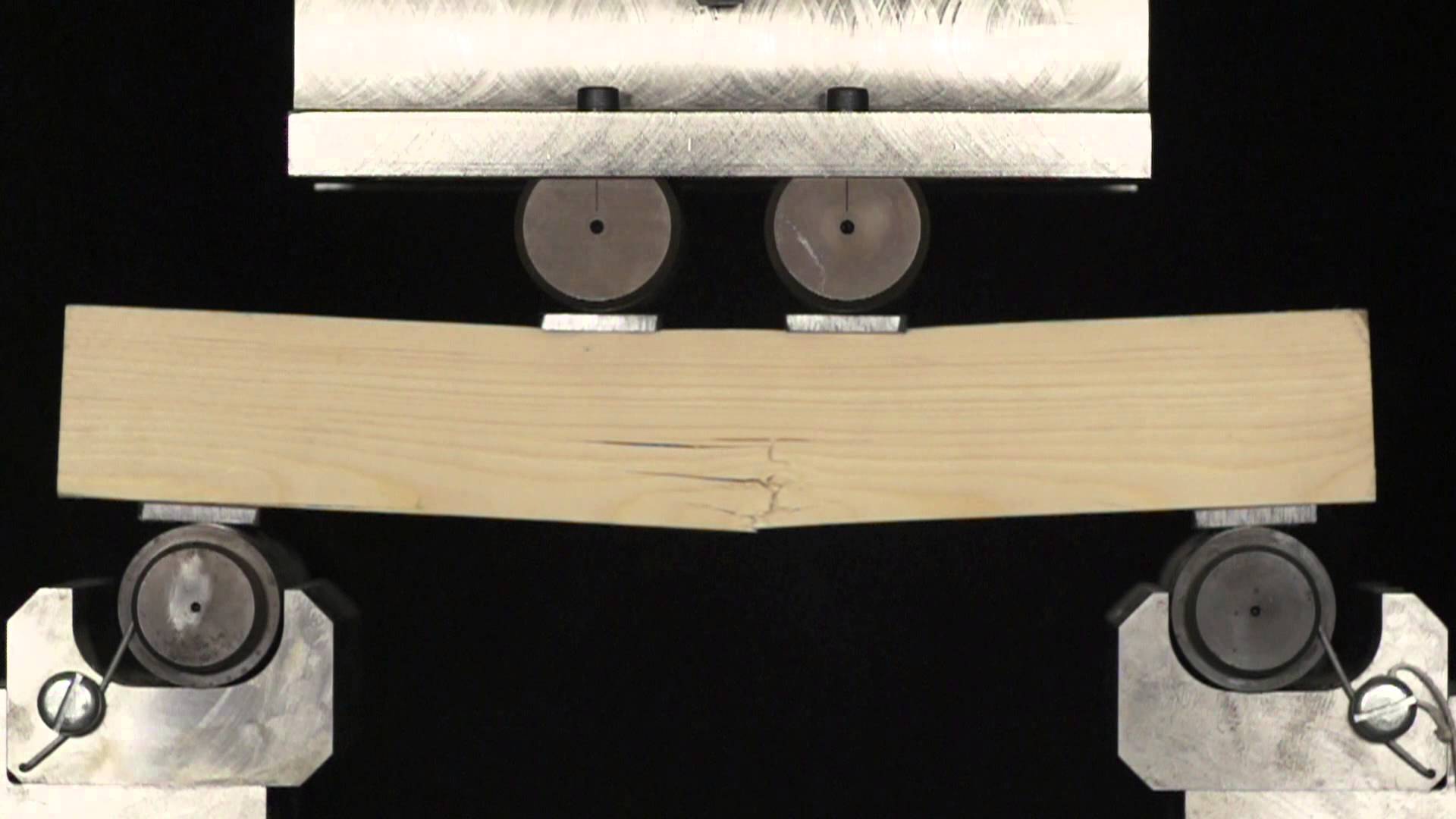
Process:
First of all, put the bending device in the UTM. Assess the density and width of the wooden beam. Regulate the support necessary for the necessary space and attach it to the lower table. Attach the transverse test pan at lower end of the lower cross head. Attach it on rollers of the transverse test brackets in such a way that the load comes at the midpoint and calculate the longitude of the span of the beam in the middle of the supports for midpoint loading. Regulate the load pointer to null by stimulating the lower table. While exerting the load, the refraction equivalent to each load is figured out from the Vernier scale on the UTM. Mark down the greatest point of deflection and the maximum load.
Calculation and Observations:
Extreme working stress in bending for wood = 15.2 N/mm2
Factor of safety (F.S) = 5
i.e., Ultimate bending stress, f-max= 15.2 x 5= 76N/mm2
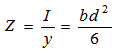
From bending equation
![]()
Z= I / y
M= f x Z
For simply supported beam with concentrated load at centre,
The singular non-identified W can be computed and thus the range can be attained.
| LOAD | DEFLECTION |
Graphs:
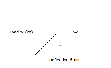
Young’s Modulus, E,
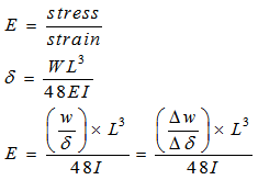
Take ![]() from the graph.
from the graph.
Modulus of Rupture. fmax
From bending equation.
M/I=f/y=E/R;
M=f.Z
For a simply supported beam with a concentrated load at centre,
Maximum Bending moment= WL/4
![]()
Where Fmax is the breaking load
RESULT:
1. Young’s Modulus of the material of the wooden beam =_______ N/mm2
2. Modulus of Rapture = __________N/mm2
Questions:
Define Modulus of Rupture.
Explain the process of calculating fiber stress because of bending in beam.
3. Explain the process to apply a non-central load on UTM in bending test.
4. Define the equation governing simple bending.
5. What do you mean by central deflection of a simply supported beam under concentrated load?
6. Explain how simple bending is incorporated in the loading arrangement.
7. Sketch showing the variation of bending stress in a beam cross-section.
8. Sketch the variation of shear stress in a beam cross-section.
9. Explain why beam are given with depth lager than width.