Aim: Assessment of the particle size distribution of soil by hydrometer method
Theory
Particle Size Distribution of Soil by Hydrometer Method
For assessment of the particle size distribution of soil by hydrometer method
Theory:
Hydrometer method is utilized for assessment fot the particle size circulation of fine-grained soils passing 75 ![]() sieve. The hydrometer computes the specific gravity of the soil deferment at the midpoint of its bulb. The specific gravity is based on the weight of solids present, which in turn is based on the particle size. The particle size (D) is expressed by:
sieve. The hydrometer computes the specific gravity of the soil deferment at the midpoint of its bulb. The specific gravity is based on the weight of solids present, which in turn is based on the particle size. The particle size (D) is expressed by:
![]()
Where,

In which, ![]() = viscosity of water in poise, G= specific gravity of solids,
= viscosity of water in poise, G= specific gravity of solids,
- = density of water (gm/ml);
 ,
,  = actual depth, t= time in minutes at which observation is noted down, reckoned with respect to the start of sedimentation.
Percentage finer than size D is expressed by:
![]()
Where R= corrected hydrometer reading, Ms= mass of dry soil in 1000ml suspension.
Equipment and tool
- Oven
- Desiccator
- Evaporating dish
- Conical flask or beaker, 1000ml
- Stop watch
- Hydrometer
- Glass measuring cylinder (jar), 1000ml
- Rubber bung for the cylinder (jar)
- Mechanical stirrer
- Weighing balance, accuracy 0.01g
- Wash bottle
- Thermometer
- Glass rod
- Water bath
- 75
![clip_image001[1]](https://civilarc.com/wp-content/uploads/2017/05/clip_image0011-1.gif) sieve
sieve - Scale
- Deflocculating agent.
Process
Part I- Calibration of Hydrometer
1. Take around 800ml of water in one measuring vessel. Put the vessel on a table and watch the underlying reading.
2. Drench the hydrometer in the vessel. Take the reading after the completion of process of immersion.
3. Decide the volume of the hydrometer ![]() which is equivalent to the distinction between the last and introductory readings. On the other hand measure the hydrometer to the closest 0.1g. The volume of the hydrometer in ml is roughly equivalent to its mass in grams.
which is equivalent to the distinction between the last and introductory readings. On the other hand measure the hydrometer to the closest 0.1g. The volume of the hydrometer in ml is roughly equivalent to its mass in grams.
4. Decide the area of cross area (A) of the vessel. It is equivalent to the volume demonstrated between any two graduations partitioned by the separation between them. The separation is measured with an exact scale.
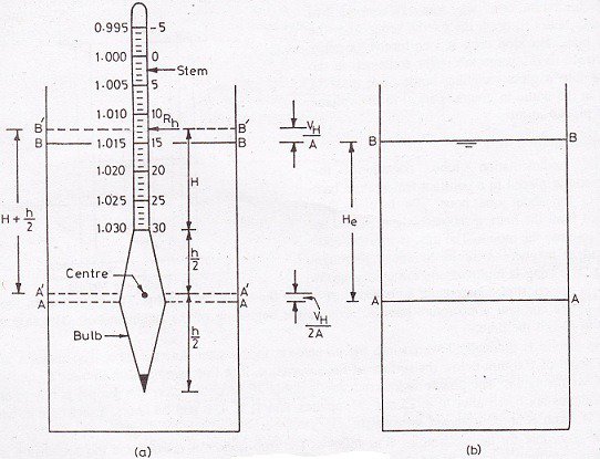
5. Measure the distance (H) between the neck and the base of the knob. Record it as the tallness of the bulb (h).
6. Measure the approximate distance (H) between the neck to every marks on the hydrometer ![]() .
.
7. Decide the effective depth ![]() relating to each of the mark
relating to each of the mark ![]() as
as
![]()
[Note: ![]() cannot be considered when the hydrometer is not taken out when taking readings after the commencement of the sedimentation at ½, 1, 2, and 4 minutes.]
cannot be considered when the hydrometer is not taken out when taking readings after the commencement of the sedimentation at ½, 1, 2, and 4 minutes.]
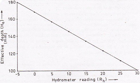
8. Draw an alignment bend amongst ![]() and
and ![]() . On the other hand, set up a table amongst
. On the other hand, set up a table amongst ![]() and
and ![]() .The bend might be utilized for finding the viable depth
.The bend might be utilized for finding the viable depth ![]() relating to reading
relating to reading ![]() .
.

Figure: Hydrometer Method

Figure: Hydrometer Calibration Chart
Part-II: Meniscus Correction
1.First of all, put the hydrometer in the measuring cylinder comprising approximately 700ml of water.
2. Note down the readings of the hydrometer at the crest and at the baseof the meniscus.
3. Regulate the meniscus correction, which is equivalent to the alteration amongst the two readings.
4. The meniscus correction ![]() is positive and is persistent for the hydrometer.
is positive and is persistent for the hydrometer.
5. The observed hydrometer reading is corrected to obtain the corrected hydrometer reading ![]() as
as
![]()
Part III- Pretreatment and Dispersion
1. Measure precisely, to the closest 0.01g around 50g air-dried soil test passing 2mm IS sieve , acquired by riffling from the air-dried specimen passing 4.75mm IS sieve.
Put the specimen in a wide tapered flagon.
2. Include around 150ml of hydrogen peroxide to the soil specimen in the flagon. Mix it delicately with a glass pole for a couple of minutes.
3. Cover the flagon with a glass plate and put it to stand overnight.
4. Warm up the blend in the cone shaped jar delicately in the wake of keeping it in a dispersing dish. Blend the substance occasionally. At the point when fiery foaming dies down, the response is finished. Diminish the volume to 50ml by bubbling. Quit warming up and cool the substance.
5. In those cases where the soil contains insoluble calcium mixes, include around 50ml of hydrochloric corrosive to the cooled blend. Blend the arrangement with a glass pole for a couple of minutes. Permit it to remain for one hour or thereabouts. The arrangement would have a corrosive response to litmus when the treatment is finished.
6. Channel the blend and wash it with warm water until the filtrate demonstrates no corrosive response.
7. Now, shift the moist soil on the filter and pipe to a dissipating dish utilizing a stream of refined water. Utilize the base amount of refined water.
8. Put the evaporating dish and its substance in a broiler and dry it at 105 to 110-degree C. Shift the dish to a desiccator and permit it to cool.
9. Take the mass of the oven dried soil after pretreatment and determine the loss of mass because of pretreatment.
10. Include 100ml of sodium hexa-metaphosphate answer for the broiler – dried soil in the vanishing dish after pretreatment.
11. Warm the blend delicately for around 10minutes.
12. Exchange the blend to the measure of a mechanical blend. Utilize a stream of refined water to wash all hints of the dirt out of the dissipating dish. Use around 150ml of water. Blend the blend for around 15minutes.
13. Shift the soil suspension to a 75 ![]() IS sifter put on a beneficiary (skillet). Wash the soil on this sifter utilizing a fly of refined water. Use around 500ml of water.
IS sifter put on a beneficiary (skillet). Wash the soil on this sifter utilizing a fly of refined water. Use around 500ml of water.
14. Shift the soil suspension passing 75 ![]() sieve to a 1000ml measuring chamber. Add more water to make the volume precisely equivalent to 1000ml.
sieve to a 1000ml measuring chamber. Add more water to make the volume precisely equivalent to 1000ml.
15. Gather the material held on 75 ![]() sieve . Dry it in a stove. Decide its mass. In the event that required, do the sieve examination of this part.
sieve . Dry it in a stove. Decide its mass. In the event that required, do the sieve examination of this part.
Part IV: Sedimentation Test
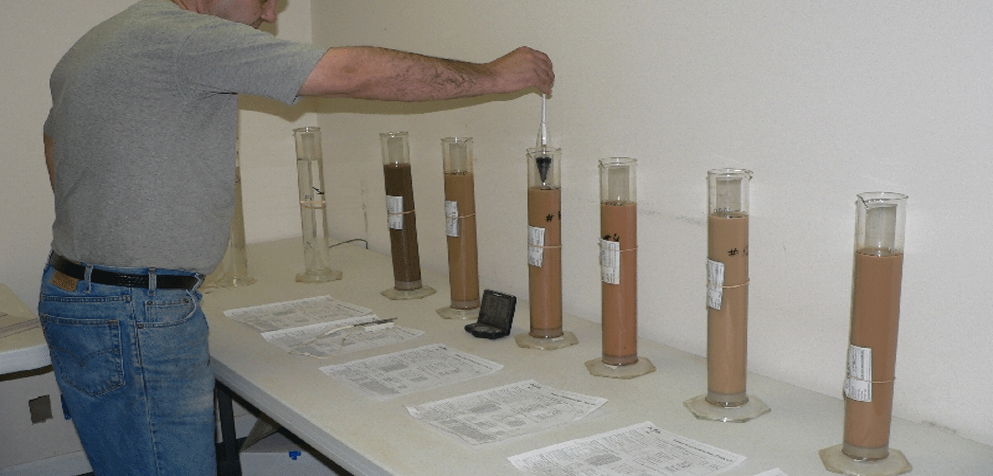
1. Put the elastic bung on the open end of the measuring barrel containing the dirt suspension. Shake it energetically end-over-end to blend the suspension altogether.
2. Evacuate the bung after the shaking is finished. Put the measuring chamber on the table and begin the stop watch.
3. Drench the hydrometer tenderly to a depth marginally beneath the gliding depth, and after that permit it to coast unreservedly.
4. Take hydrometer deciphering ![]() 1/2, 1, 2 and 4 minutes without expelling the hydrometer from the chamber.
1/2, 1, 2 and 4 minutes without expelling the hydrometer from the chamber.
5. Take out the hydrometer from the chamber, wash it with refined water.
6. Float the hydrometer in another cylinder containing just refined water at an uniform temperature from that of the test vessel.
.7. Take out the hydrometer from the refined water chamber and clean its stem. Embed it in the vessel containing suspension to take the perusing at the aggregate slipped by time interim of 8minutes. Around 10 seconds ought to be taken while taking the perusing. Expel the hydrometer, wash it and place it in the refined water subsequent to reading.
8. Continue the progression (7) to take readings at 15, 30, 60, 120 and 240minutes slipped by time interim.
9. Following 240 minutes (4 hours) reading, take readings twice inside 24 hours. Correct time of perusing ought to be noted.
10. Record the temperature of the suspension once amid the initial 15minutes and from that point at the season of each ensuing reading.
11. After the last reading, pour the suspension in a dissipating dish, dry it in a stove and locate its dry mass.
12. Decide the composite revision before the begin of the test and furthermore at 30min, 1, 2 and 4 hours. From that point soon after every reading, composite remedy is resolved.
13. For the ascertaining of composite revision (C), embed the hydrometer in the examination barrel containing 100ml of scattering specialist arrangement in 1000 ml of refined water at a similar temperature. Take the reading relating to the highest point of meniscus. The negative of the perusing is the composite amendment.

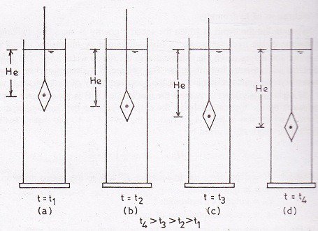
Figure: Downward Movement of Hydrometer
Data Sheet for Hydrometer Test
Mass of dry soil (Ms)=_______g
Meniscus correction (Cm)= +_______
Specific gravity of solids (G)= ______
| OBSERVATIONS
|
CALCULATIONS
|
|||||||||
| Elaspsed time
|
Hydrometer reading
|
Temp-
erature
|
Composite correction
|
Corrected reading
Rh=Rh’+Cm
|
Height
(cm) He
|
Reading R= Rh’+C
|
Factor
M
|
Particle size
D
|
%
Finer
|
|
| 1
|
1/2min
|
|||||||||
| 2
|
1 “
|
|||||||||
| 3
|
2 “
|
|||||||||
| 4
|
4 “
|
|||||||||
| 5
|
8 “
|
|||||||||
| 6
|
15 “
|
|||||||||
| 7
|
30 “
|
|||||||||
| 8
|
1 hr
|
|||||||||
| 9
|
2 hr
|
|||||||||
| 10
|
4 hr
|
|||||||||
| 11
|
8 hr
|
|||||||||
| 12
|
12 hr
|
|||||||||
| 13
|
24 hr
|
|||||||||
Result:
Particle Size distribution curve can be plotted using the last two columns.

