Objective:
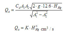
(i) To standardize the tool (by assessing the constants K and n, presuming the actual discharge Qa = K HHg n )
(ii) To decide on the coefficient of discharge (Cd) of specified Venturi meter for diverse rates of flow.
(iii) To assess the difference of Cd and discharge in regards to the head by plotting the next graphs
Cd Vs HHg
Log Qa Vs Log HHg (to find K and n )
Qa Vs HHg (utilizing K and n values)
Basics:
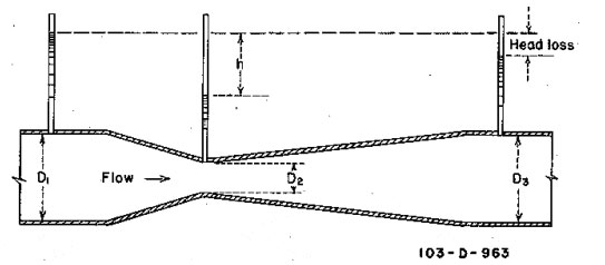
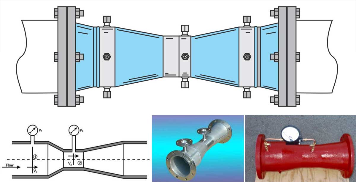
Venturimeter is an equipment utilized for determination of the speed of flow of a fluid flowing through a pipe. Water is permitted to flow through the meter at various rates ranging from zero to the highest and the parallel pressure differences given in the manometer are marked. The real discharge Qa is ascertained utilizing the measuring tank and the stop watch.

Actual discharge

Where
a – Area of measuring tank in cm2
h – Height differences in piezo meter in cm
t – Time period to collect water for a height difference of h cm, measured in
seconds
Theoretical discharge

Where
A1 – The area at inlet side in cm2
A2 – The area at throat in cm2
Hw – Head difference in the manometer, converted to cm² of water
g – Acceleration because of gravity (9.81m/sec²)
Coefficient of discharge

Observation:
| Sl.No | Time for 10cm rise of water level (s ) | Actual discharge Qa. cm3/s | Differential head in cm. of mercury | Differential head in cm. of water | Theoretical discharge Qth, cm3/s | Coefficient of discharge Cd | |||||
| h1 | h2 | h1– h2
HHg |
|||||||||
| t1 | t2 | tm | |||||||||
|
1
2
3
4
5
|
|||||||||||
Calibration table
| Sl No | HHgin cm | Hw in cm | Qa in cm3/ s | Log Qa | Log HHg | Actual discharge
Qa = KHHgn |
| 1
2 3 4 5 |
Calibration
Amenities for creating standardized flows are necessary for flow meter calibration. When the basic flow input is accessed via the determination of time and either linear dimension, which is volumetric flow, the process is known as primary calibration. After the completion of primary calibration, a meter may then be utilized as a secondary standard for standardizing other meters via the method of comparative calibration.
The Equation

And

Procedure
(i) Shut all of the valves of inlet pipe, venturimeter pipe and manometer tube.
(ii) Choose the venturimeter pipeline in which the experiment is to be carried out and unlock the corresponding valve.
(iii) Open the inlet valve.
(iv) Open up the needle valves of manometer and venturimeter tubes. Make sure that the manometer is prepared to confiscate any air bubbles present in it.
(v) Regulate the valve at the exit side of the venturimeter pipe to a needed flow rate.
(vi) Mark down the readings of manometer and time required for 10 centimeter rise of water in measuring tank.
(vii) Regulate the gate valve for a new flow rate and conduct the experiment again.
Maintenance
- After the completion of the experiment shut the inlet valve and open up all the gate valves and needle valves to vent any air which is rapt inside and then close them.
- Deplete the water from measuring tank after the completion of the experiment.
Result:
Inference:

