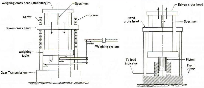
Universal testing machine (UTM) is known as so due to the great resourcefulness of its application. The following tests can be executed with it:-
- Tension Test.
- Compression Test.
- Bending Test.
- Hardness Test
Description
The Universal Testing Machine comprises of two chief parts which are the loading unit and the control panel.
Loading Unit
The loading unit comprises of a strong and robust foundation at the core of which is connected the main cylinder and piston. A rigid frame comprising of the lower table, the upper cross head and additionally the two straight columns is fixed to this piston with the help of socket joint and ball. Two screwed columns connected on the base will pass through the chief nuts to back the lower cross-head. This cross head is shifted either up or down when the screwed columns are switched by a geared motor connected to the foundation. Each cross-head has a narrowing slot at the midpoint into which at least two racked jaws are inserted. These jaws are shifted either up or down by the functioning handle on the cross-head face and is projected to carry the plate (grip) jaws for the tensile experiment sample. An elongation scale, which calculates the relative movement amongst the lower table and the lower cross-head, is also given with the loading unit.
The Control Panel
The control panel comprises of the hydraulic power unit, the load computing unit and the control equipment.
1. Hydraulic Power Unit
The Hydraulic Power Unit basically comprises of an oil pump driven with sump and electric motor for hydraulic oil. The pump that support is of reciprocating kind, including a set of plungers which ensures of a constant non-pulsating oil flow inside the chief cylinder for an efficient utilization of the test load on the sample. Hydraulic lines of the unit are of an unusual configuration to allow them to execute wide range of functions.
2. Load Measuring Unit
The load measuring unit, basically refers to the pendulum dynamometer unit. It consists of a minute cylinder in which a piston shifts in phase with the chief piston under the similar oil pressure. A meek pendulum fixed or attached with this minute piston with the help of a pivot lever, consequently rebounds in agreement with the load on the example and the pivot proportion. This rebound is conveyed to the load pointer which shows the test load on the dial. The pivot lever consists of four fulcra -knife-edges, thus providing fo4ir ranges of test load, (which are 0-100 kN; 0-250 kN; 0-500 kN and 0-1000 kN). The mandatory range can be designated by the process of turning a knob specifically given to fulfill this objective. The general precision of the machine chiefly is based on the precision of the computing unit.
3. Control Devices
These comprises of the electric control devices, the hydraulic control devices and the load indicating devices.
The Electric Control Device
The Electric Control Devices are basically in the configuration of four switches positioned on the left side of the panel face. The upper and lower push switches are mainly utilized for moving the lower cross-head up and down in succession. The two which are left are the ON and OFF switches utilized for the operation of hydraulic pump.
The Hydraulic Control Devices
The Hydraulic Control Devices refers to the pair of control valves which are positioned on the control panel table. The right control valve refers to the inlet valve. It is a pressure compensated flow control valve and additionally has an already constructed overload relief valve. In those cases, where the valve is in the shut position, whereas the hydraulic system is turned on, oil will flow back into the sump. Opening of the valve now, will lead the oil to flow into the chief cylinder in a constant non-pulsating method. The left control valve is also known as the return valve. In those cases, where the valve is in the closed position, the oil pumped into the chief cylinder will lead to the chief piston to shift upwards. The chosen sample repels this movement, right after it becomes loaded up. Oil pressure on the exterior of the chief cylinder (and elsewhere in the line) will then commends to expand up until either one of the sample gets broken or the load extents to the greatest value of the range chosen. A gradual opening of this valve will now lead the oil to drain right back into the sump and consequently, the chief piston to descent.
The loading indicating devices
The Load indicating Devices comprises of an assortment range inflating dial positioned after a load representing dial. The first one shifts and sets itself to the range chosen when the range regulating knob is turned. The load exerted on the sample at any given stage is represented by the load pointer which shifts over the load showing dial and harries onward with it a dummy.

