
Aim: to prove Bernoulli’s Theorem
Tool:
Stopwatch
Measuring tank
An apparatus for verification of Bernoulli’s theorem
Basics:
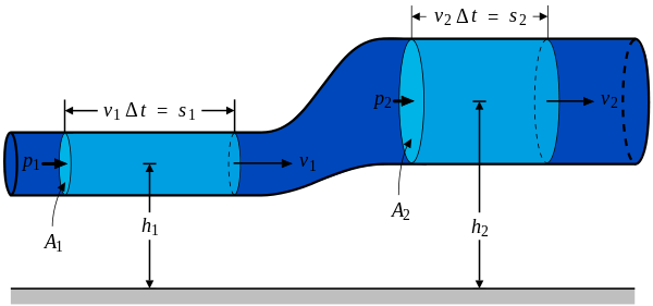
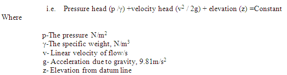
Bernoulli’s theorem says that for a stream lined, steady, incompressible and exclusive of friction fluid flow, the total of pressure head, velocity head and potential head have to be uniform.
Water or any other liquid at constant head from a tank is permitted to pour through a level pipe line of changeable cross section. The pressure heads Hp1,Hp2, are marked from piezometers put at the cross sections A1,Aa2Etc .By thoroughly measuring the real discharge ,the real velocities of flow at A1,A2 etc are assessed.
Actual discharge
![]()
Where
- Area of measuring tank in cm 2.
h- Level disparity of water in the measuring tank in cm.
tm-The mean time taken to collect water
The velocity of flow at the cross section A1 is specified by
![]()
The speed head
![]()
That the pipe line has negligible frictional loss in flow , Bernoulli’s equation for the horizontal pipe at cross section A1, can be proved as :
Pressure head Hp1+ velocity head Hv1=constant
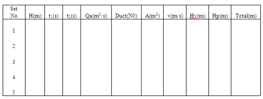
Observations:
Constants:
Areas of cross section A1, A2 and etc
Measuring Tank
The height for which the time t1 and t2 are marked to gather water in the measuring tank.
Variables
- The piezometer readings HP1,HP2 etc in m of water
- Time tm seconds obtained to accumulate water for a stature of h m in the measuring tank as the mean value of readings t1 and t2
Process
- Unlock the inlet valve to supply tank and permit the water to fill to a maximum head of H m.
- Open the outlet valve of the apparatus to have water pour through the testing pipe. Then adjust both the inlet and out let valves so that it leads the head H is put constant. This state is obtained in situations which the inlet is equivalent to outlet.
- Mark the time in seconds to gather water for a increase of h m in the measuring tank twice as t1 and t2.If the dissimilarity in readings is greater 10%, once again conduct a third reading inside the range.
- Mark the pressure head Hp at the cross sections A1,A2 etc.
- Conduct the experiment for again and again for the medium and low heads in supply tank.
Result:
Inference: