
To assess the shear strength of a sandy soil sample by direct shear test:
Theory
Shear strength of a soil is its maximum resistance to shearing stresses. The shear strength is given as:
![]()
Where,
c’ = effective cohesion,
- = effective stress,
 = effective angle of shearing resistance.
- The shear tests could be undertaken under three varied drainage conditions. The direct shear test is normally carried out on sandy soils as a combined drained test.
Equipment:
- Loading pad
- Loading frame
- Loading yoke
- Proving ring, capacity 2kN.
- Dial gauges, accuracy 0.01mm, 2 Nos.
- Static or dynamic compaction devices.
- Shear box, divided into two halves by a horizontal plane, and fitted with locking and spacing screws
- Box container to hold the shear box
- Base plate having cross grooves on its top surface
- Grid plates, perforated, 2 Nos.
- Porous stones, 6mm thick, 2 Nos.
Process
1. Measure the inside measurements of the shear box. Likewise decide the normal thickness of the grid plates.
2. Fix the upper part of the crate to the lower part utilizing the locking screws. Connect the base plate to the lower part.
3. Put the grid plate in the shear box putting the serrations of the matrix at right edges to the direction of shear. Put the permeable stone over the grid plate.
4. Measure the shear box with base plate, grid plate and permeable stone.
5. Put the soil example in the case. Pack it straightforwardly in the shear box at the required thickness. At the point when the soil in the top portion of the shear box is filled up to 10 to 15mm profundity, level the soil surface.
6. Measure the case with soil sample.
7. Measure the weight of the case inside the crate contained and settle the stacking pad on the container. Mount the crate contained on the stacking outline.
8. Bring the upper portion of the case in contact with the demonstrating ring. Check the contact by giving a slight shaking.
9. Fill the holder with water if the soil is to be immersed, generally overlook this progression.
10. Mount the loading yoke on the ball put on the loading pad.
11. Mount the dial gauge on the loading yoke to record the vertical relocation and another dial gauge on the holder to record the flat displacement.
12. Put the weights on the loading yoke to apply an average stress of 25 ![]() . Permit the sample to solidify under the applied regular stess. Take note of the vertical displacement dial gauge.
. Permit the sample to solidify under the applied regular stess. Take note of the vertical displacement dial gauge.
13. Detach the locking screws. Utilizing the spacing screws, raise the upper part marginally over the lower part with the end goal that the hole is somewhat bigger than the greatest particle measure. Evacuate the spacing screws.
14. Change all the dial gauges to mark zero. The demonstrating ring ought to likewise read zero.
15. Apply the level shear stack at a consistent rate of strain of 0.2mm/moment.
16. Mark down the reading of the demonstrating ring, the vertical displacement dial gage and the level displacement dial gage at consistent time interims. Take the initial couple of readings at nearer interims.
17. Proceed with the test till the samples falls flat or till a strain of 20% is come to.
18. Toward the finish of the test, expel the sample from the container and take an agent test for water content assurance.
Carry on the test on uniform samples under the regular stresses of 50, 100, 200, 400 and so on. (The scope of stresses chose ought to relate to the real field stress conditions.)
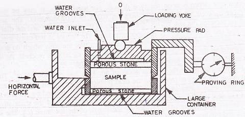
Figure: Direct Shear Test Apparatus
Data sheet for direct shear test
Size of the box =
Area of the box =
Thickness of the specimen =
Volume of the specimen =
Mass of soil specimen =
Bulk density =
Water content =
Dry density =
Void ratio =
Tare mass of hanger =
Mass of hanger
Total mass =
Normal stress =
Mass of box + base plate + porous stones + grid plate =
Mass of box + base plate + porous stone + grid plate + soil specimen =
Plot the Coulomb envelope between the normal stress as abscissa and shear stress at failure as ordinate.
Result:
From plot, c’ =
![]()