
Objective:
(i) For ascertaining the coefficient of expulsion (Cd) of the specified notch for diverse rates of flow
(ii) To standardize the notch (by shaping the constants K and n, presuming the actual discharge Qa = K Hw)
(iii) To plot the specified graphs:
Cd Vs Hw.
Log Qa Vs Log Hw (to locate K and n value)
Qa Vs HHg (by means of K and n values)
Equipment:
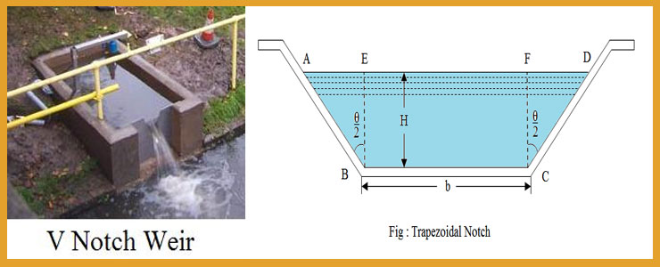
- a) The specified rectangular and triangular notches (600)situated on the unlocked channel of the tentative setup. The channel has steady agreement with baffles and condition for fixation of the exchangeable notch plates. The steadying region is overflowing with 25mm or 40mm ballets to recieve stable flow.
- b) Hook gauge is kept on the notch tank’s top edge, which has to be positioned in the parallel position with the contribution of spirit level. It is utilized for assessing the deepness of water.
- c) Measuring tanks of respective Size 0.8 x 0.8 x 0.8 meter with arrangement for overflow, scale arrangement, gauge glass and a drain valve to calculate the definite discharge.
- d) Stop watch.
Theory:
Water is allowed to flow over the notch at different rates ranging from zero to the maximum possible level and the corresponding head over notch shown in the hook gauge are noted. The actual discharge Qa is determined using the measuring tank and the stop watch.
The actual discharge,
Qa = a x h / tm
Where
a – area of measuring tank in cm2
h – level difference of water in the measuring tank in cm.
Tm — The mean time to collect water for a height difference of h cm, measured in seconds (tm = 60 to 120 s)
The theoretical discharge is assessed by marking the ‘head’ (H) over the notch plate, computed by the means of the hook gauge. For wide assortments of Notch plates, diverse formulae have to be utilized to compute the notional quantities of flow.
For a rectangular notch
Where
Qt – Theoretical discharge
B – Breadth of the notch
H – Head of water over the notch
g – Acceleration due to gravity = 9.81.
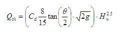
For a ‘V’ Notch
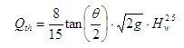
Where
Qt – Theoretical discharge
H – Head of water over the notch
g – Acceleration due to gravity = 9.81.
? – Angle of notch (600)
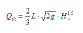
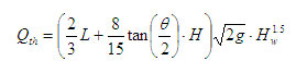
For a trapezoidal notch
| Sl. No | hook gauge reading | Time for 10 cms raise of water level in s
|
Theoreticaldischarge
Qth |
Actual dischargeQa | Cofficient of discharge
Cd= Qa/Qt |
||||
| InitiaLl | Final | Depth | t1 | t2 | meantm | ||||
|
1
2
3
4
5
|
|||||||||
| Sl. No | Head of water Hw | Theoreticaldischarge
Qth |
Cofficient of discharge
Cd |
Log Hw | Qth = KHwn | Actual dischargeQa |
| 1
2 3 4 5 |
Calibration
All of the measuring techniques have to be provable, that is, it should be able to prove its aptitude to calculate reliably. The process is also known as Calibration. It incorporates the determination of the system’s scale.
Amenities for creation of the standardized flows are compulsory for flow meter calibration. Fluid at different rates of flow has to be passed via the meter and the rate in comparison with the meter.
Read out. When the vital flow input is resolute via the assessement of time and whichever linear proportions, that are volumetric flow, the process is known as the primary calibration. After the primary calibration, a meter may then be utilized as a resultant standard for standardizing other meters via the process of comparative calibration.
The equation
Qa = Cd x Qth can be written as,
i.e. Qth = K x Hwn
Where
K represents the bracketed terms.
After taking logarithm on both sides, log Qa = log K + n * log Hw. The graph log K vs log Qa will be consequently plotted. Taking from the straight line graph, the y – intercept will give a log K and the incline of the line given n. After finding K and n values, the calibration graph Qa vs Hw is illustrated. (Here,
Hw is the reading as expressed on hook gauge. This will lead to obtain the Qa principles openly parallel to the head over notch.)
- Choose the suitable notch plate and fasten it at the notch holder. Fill up the liquid in the notch channel until it starts to overflow and recieve the still level reading H1utilizing the hook gauge
- Unlock the inlet valve to the required value of flow. Permit water to pour over the notch at the highest feasible level by channelizing the inlet valve and mark the reading in hook gauge as H2cm. Then obtain the maximum head over the notch Hw = (H2-H1) (While the inlet vave is completely open) and segregate the value into roughly seven equivalent divisions in order to fasten the steps in the head over notch for seven sets of the readings.
- Regulate the inlet valve to obtain the maximum head over notch, then let it be for few minutes for the head over notch to turn out to be unvarying and subsequently note the hook gauge reading H2
- Mark the time to accumulate water for raise of h cm in the measure tank two times as t1and t2seconds. If the dissimilarity in time is greater than 10%, conduct next reading which results inside this permissible range.
- Replicate the trial for various heads over notch by regulating the inlet valve and tabularize the observations
Maintenance:
- After the completion of the experiment deplete the water from the notch tank and measuring tank.
- Grease the hook gauge.
Results:
Inference: